Session III - Rehabilitation
The Use of the "No Angulation View" for Single Oblique Cut - Corrective Osteotomies of Complex Tibial Malunions
J. Spence Reid, MD; Brian Nielsen, MD; Gregory Gilot, MD; Paul Juliano, MD; Erin Moran, Pennsylvania State University College of Medicine, Hershey, PA
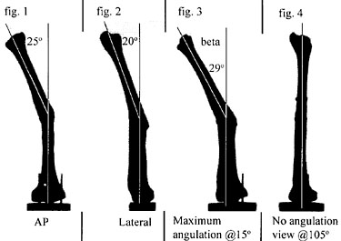
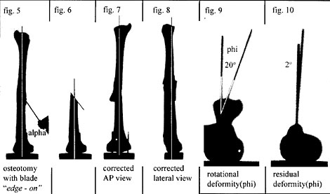
Purpose: Post-traumatic tibial malunions in which angulation can be visualized on both the AP and lateral radiographs have been described as multiplanar (fig. 1 and 2). As several authors have reported1-4, these angular deformities are not really multiplanar because, in each case, the true plane of maximum angulation can be easily determined by a graphical or trigonometric transformation. This plane of maximum angulation lies at an intermediate oblique projection between AP and lateral (fig 3). The radiographic projection orthogonal to the plane of maximum angulation yields a straight but foreshortened image we have termed the "no angulation view" (fig. 4). Malrotation along the axis of the shaft is also frequently present. In many deformites that involve angulation and axial rotation, there exists a unique oblique plane through the center of rotation angle (CORA) of the deformity that will allow complete correction by rotation in this plane. Surgical correction of the deformity by this method is advantageous in that it creates broad bone surfaces through the oblique cut that heal readily and easily accommodate an interfragmentary screw. The difficulty in clinical application of this method of deformity correction lies in appropriate preoperative patient selection and intraoperative execution of the oblique cut. We have determined that the oblique cut is always in the plane of maximum angulation. This greatly simplifies execution of the technique. Intraoperatively, the c-arm is rotated until a no angulation view with the CORA in the center of the screen is obtained. The cutting blade is oriented on edge in this view (fig. 5). The angle of the blade with respect to the shaft axis is determined preoperatively through the trigonometric relationship between the maximum angulation of the deformity and the degree of malrotation determined either clinically or by CT scan. The accuracy of this technique of deformity correction was tested using sixteen plastic bone models in which angular and rotational deformities had been created. Interobserver variability in the determination of the no angulation view was also tested.
Methods: A special cutting jig was made to axially align each plastic tibia. The AP plane was defined as parallel to the plane tangent to the posterior condyles of the proximal tibia. The lateral plane was orthogonal to the AP. Prior to creation of the deformity, 5 millimeter alignment rods were placed into the proximal and distal metaphysis of each model in the sagittal plane and parallel to each other. These rods were used to determine the axial rotation of the proximal and distal tibial segments before and after corrective osteotomy. Eight combinations of varus/valgus/procurvatum/recurvatum and internal/external rotation were selected. For each combination, the axial malrotation was set at both 20 degrees and 30 degrees, which yielded sixteen different deformed specimens. A c-arm image was simulated by using a light source directed at a semilucent screen with the tibial model oriented vertically upside down on a calibrated turntable. Rotation was about a longitudinal axis through the center of the proximal segment. A camera was mounted on the opposite side of the screen to record the projected images. The light source-to-specimen distance was 8 feet; the specimen-to-screen distance was 6 inches and the camera-to-screen distance was 32 inches. Angles were measured from 8 x 10 inch enlargements of the photographed projections using a protractor (+/- 1°).
Each specimen was mounted, and an AP and lateral projection was recorded by rotating the calibrated turntable. Then, the no-angulation view (fig. 4) was determined visually by rotating the turntable until the tibial model looked clinically straight. The maximum angulation view was orthogonal to this view and was obtained next. The angulation of the tibia in this view (beta) was measured from the semilucent screen. The equation alpha = arctan(phi/beta) where phi is the premeasured rotational deformity of the specimen and alpha(fig. 5) is the angle of the osteotomy blade with respect to the axis of the tibial shaft was generalized from Rab4. From this equation, alpha is determined. The osteotomy was then performed while visualizing the no-angulation view and bringing the blade of the oscillating saw to the shaft at the angle alpha with the blade of the saw on edge in this view (fig 5). Upon completion of the cut, the distal aspect was rotated in the plane of the cut until the AP view was anatomic and clamped. The specimen was then glued in this position, and AP and lateral projections were then recorded (fig. 7 and 8). Residual angular deformity (beta) was measured in these projections. The residual rotational deformity (phi) was determined by obtaining an axial projection of the specimen after replacing the 5mm alignment rods (fig. 9 and 10).
Results: The tibial deformities with an initial 30 degree axial malrotation had an average residual rotation of 9°(3 - 15°). Those specimens with an initial 20 degree malrotation had an average residual of 3°(0 7°). The residual angulation in the AP plane for all 16 specimens averaged 2° (0 - 6°). The residual lateral angulation averaged 3° (0 11°). The error in performing the osteotomy at the planned angle alpha averaged 7' (0° to 12°) and 40 (+6° to 6°) in those specimens with initial malrotations of 30° and 20° respectively. This error in proper execution of the osteotomy angle was the most important contributor to residual rotational deformity. Ten orthopedic residents were asked to visually select the no-angulation view and maximum angulation view for 2 deformed specimens. In each case, the variance in judging the no-angulation view (4.1 specimen I, 23.8 specimen II) was smaller than the variance in judging the maximum angulation view (113.7 specimen I, 70.0 specimen II).
Discussion and Conclusions: There are several prerequisites for the use of this technique for the correction of a tibial posttraumatic deformity. The deformity must have both rotation and angulation. A pure angulatory malunion is probably best handled with other methods, as this technique will induce unwanted rotation in the tibia. The linking of rotational and angular correction is inherent in this method but was not emphasized in the paper by Sanders et al1. Sources of error in our method include the visual alignment of the saw during cutting. This error averaged about 5 degrees, but these authors suspect this error will worsen in an intraoperative setting. The effect of parallax in the c-arm image was not addressed in this study. Despite these limitations, the use of the no-angulation view simplifies this osteotomy substantially. Once this view is obtained, only two parameters need to be controlled, the angle of the cut (alpha) and keeping the blade "end on" in the center of the c-arm image. Deformities with 20 degrees rotational malalignment appear to be more fully corrected than those with 30° rotational malalignment.
Bibliography-
1Sanders, R., Anglen, J.0., Mark, J.B. Oblique Osteotomy for the Correction of Tibial Malunion. J Bone.Jont Surg., 77A: 240-246, 1995.
2Sangeorzan, B.J., Sangeorzan, B.P., Hansen, S.T Judd, R.P. Mathematically Directed Single Cut Osteotomy for Correction of Tibial Malunion. J Orthop. Trauma 3:267-275, 1989.
3Johnson, E.E. Multiplane Correctional Osteotomy of the Tibia for Diaphyseal Malunion. Clin. Orthop. Rel. Res. 215: 223-232, 1987.
4Rab, G.T. Oblique Tibial Osteotomy for Blount's Disease (Tibia Vara) J. Pediatric Orthop. 8:715-720.